What Is the ECS?
Most users know that the UCS stands for User Coordinate System, that ECS
stands for Entity Coordinate System, and that every AEC object has an
ECS.
To turn on the ECS:
1. Select Desktop
> Display Manager from the main menu to bring up the Display Manager.
2. In the Display
Manager, expand the Representations by Object tree.
3. Select Anchor
Free from the expanded list to bring up its Display Representations.
4. Click the word
General; right-click and choose Select All from the contextual
menu that appears (see Figure 8).
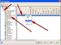
Figure 8: Choose Select All from the contextual menu.
(click image to enlarge)
5. Click the Apply
button, and then click OK to close the Display Manager.
6. Zoom close to
the horizontal column that your node anchored to the layout grid.
7. Select the
horizontal column, right-click, and select Node Anchor > Release from
the contextual menu (see Figure 9). This operation releases the
horizontal column from the layout grid.
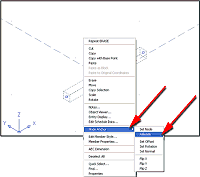
Figure 9: Select Node Anchor > Release from the contextual menu.
(click image to enlarge)
Notice that both
the layout grid and the column have a red, green, and yellow indicator.
The red has one arrow, the yellow has two arrows, and the green has
three arrows. These indicator arrows define the column's ECS (Entity
Coordinate System) (see Figure 10).
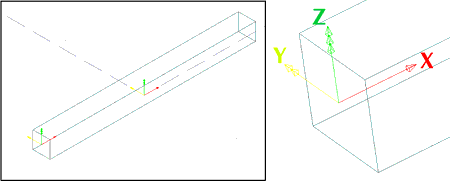
Figure 10: The column's ECS (Entity Coordinate System).
In columns, the X
direction of the ECS is always along the length.
When anchoring
columns to a layout grid, the column ECS always matches the layout grid
ECS. This is why the column was placed horizontally when anchored to the
layout grid.
When using a
column grid with automatically attached columns, the Autodesk
Architectural Desktop programmers made the column Normals and Rotation
change automatically to make the columns perpendicular to the column
grid.
The Reference
Object
1. Move the released column away from the layout grid.
2. Select Desktop
> Utilities > Reference AEC Objects from the main menu.
3. Enter Ad
for Add in the command line and press the Enter key.
4. Select the
released column when prompted to "Select an entity to reference" in the
command line.
5. Select the
bottom of the released column with an Insertion Object snap. A column
reference object is created.
6. Move the column
reference object to the side of the released column, and accept the
default rotation angle of <0.00> by pressing the Enter key. Press the
Enter key again to complete the command.
7. Select Desktop
> Anchors > Node Anchor from the main menu.
8. Enter A
for Attach object in the command line and press the Enter key.
9. Select the
column reference object, select a node in the layout grid, and press the
Enter key again to close the REFERENCE AEC OBJECT command. The column
reference object is now attached to the layout grid node.
10. Zoom close to
the column reference object, which is now attached to the layout grid
node. Notice the X, Y, and Z direction of the ECS (see Figure 11).
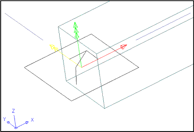
Figure 11: The column reference object's ECS (Entity Coordinate
System).
11. Select the
column reference object and right-click to bring up its contextual menu.
12. Select Node
Anchor > Set Rotation from that menu.
13. Rotate the
column around the Y-axis:
- Accept the X
angle rotation of 0,00 in the command line and press the Enter key.
- Enter -90
for the Y angle rotation and press the Enter key.
- Accept the Z
angle rotation of 0,00 in the command line and press the Enter key to
rotate the column reference object.
Copying Columns
on Each Node
14. Select Desktop > Anchors > Node Anchor from the main menu.
15. Enter C
for COPY to each node in the command line, and press the Enter key.
16. Select the
column reference object you placed in Step 9, and then select the layout
grid.
17. Enter Y
in the command line to skip nodes that already have objects anchored to
them, and press the Enter key twice to complete the COPY command.
The column
reference object now propagates any changes you make to the original
column to all the other columns in the drawing.
18. Select the
original horizontal column and right-click to bring up its contextual
menu.
19. Select Member
Properties from that menu to bring up the Structural Member Properties
dialog box.
20. On the
Dimensions tab change the A- Start Offset to 5'-0" and the C-Length to
20-'0", and then select the Trim Planes tab
21. On this tab
add a trim plane, offset from the End (in drop down list), and rotate it
45 degrees around the Y-axis. Click and then click OK to complete the
command (see Figure 12).
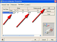
Figure 12: Adjust the column reference object's trim plane.
(click image to enlarge)
By changing the
column for which you created the column reference object, all the
columns change (see Figure 13).
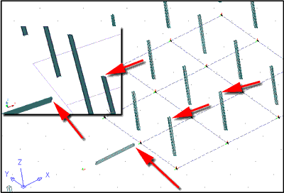
Figure 13: By changing the column for which you created the column
reference object, all the columns change.
Conclusion
When you understand some of the underlying concepts that drove the
development of AutoDesk Architectural Desktop 3.3, you'll better utilize
the software's capabilities. The REFERENCE AEC OBJECT command gives you
significant control of drawing objects. Use it with all AEC objects, and
you'll reduce errors and improve your productivity.
Good Luck, Ed
Goldberg
|