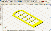
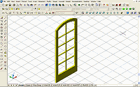
To print: Click here or Select File and then Print from your browser's menu
Architectural Desktop: Customizing Doors
by: Ed Goldberg
URL: http://pointa.autodesk.com/gotoPointA.jsp?dest=15823
While I'm waiting for more door and window manufacturers to add i-drop®-enabled content for use in Autodesk® Architectural Desktop 3.3, I often go ahead and create my own. Autodesk Architectural Desktop 3.3 offers an easy and comprehensive method for creating this custom Style content. If you go to the Point A Download Center, you will find customized doors and windows created by numerous Architectural Desktop users. Why not download some of these styles and open them up to see how they have been created? (Be sure to save any blocks or components from these Styles to help in your own customizations.) But in this tutorial, I'll show you how I go about creating a custom door Style. And keep in mind that creating Styles can greatly enhance your productivity.

For this tutorial I selected an ARCH TOP FRENCH door manufactured by Marvin.

Creating the Door and Jamb Components
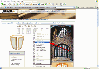
1. Go to the Marvin site page with the following URL:

http://architect.marvin.com/products/productDetails.cfm?oid=83B570AD-C666-4E4E-92911A718E5E524A

2. Right-click on the page, and select Save Picture As from the shortcut menu that appears.

3. Accept the default name and place it in a convenient directory on your PC (see Figure 1).


Figure 1: Go to the Marvin site page.
(click image to enlarge)

The image you have saved is a raster (bit-mapped) GIF file of Marvin's Arch Top French Doors (see Figure 2).


Figure 2: Raster (bit-mapped) GIF file.

4. Start a new Autodesk Architectural Desktop 3.3 drawing using the Aec arch [imperial] template, and select the Work 3D layout.

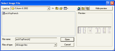
5. Select Insert > Raster Image from the Main menu to bring up the Select Image File dialog box (see Figure 3).


Figure 3: Insert the raster image in Architectural Desktop.

6. In this dialog box select the archTopFrench GIF file you just saved from the Marvin website.

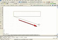
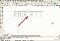
7. Click anywhere on the screen, drag the cursor, and click again to set the image size (size doesn't matter) (see Figures 4 and 5).


Figure 4: Drag the cursor to size the image.
(click image to enlarge)


Figure 5: Click the mouse to set the image.
(click image to enlarge)

You have now placed the GIF file your Architectural Desktop drawing.

8. Create a new layer called Raster.

9. Select the GIF and choose Raster layer from the Layer drop-down list to place the GIF on the Raster layer.

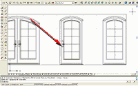
10. Zoom window around the second door from the right (see Figure 6).


Figure 6: Zoom window around the door.
(click image to enlarge)

11. Select the image, right-click, and select Image Clip from the contextual menu.

12. Select New boundary from the Command line and press the Enter key.

13. Select Rectangular from the Command line and press the Enter key.

14. Create a window selection around the door and click the mouse.

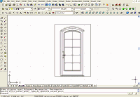
You have now isolated the door image we want to use (see Figure 7). The next process is to trace it (see Figure 7), which you begin by scaling the GIF.


Figure 7: The clipped image.
(click image to enlarge)

To scale the GIF for tracing:

15. Select the Scale icon from the Modify toolbar, select the GIF, and press the Enter key.

16. Click at the lower-left corner of the door when prompted to specify a base point at the Command line.

17. Enter R (for Reference) in the Command line and press the Enter key.

18. Click at the lower-left corner and then at the lower-right corner of the door.

19. Enter 3' at the Command line when prompted to specify a new length, and press the Enter key.

The GIF is now correctly scaled for tracing.


To trace the GIF:

20. Lock the Raster layer.

21. Create three new layers named Jamb, Door, and Mullions.

22. Make the Jamb layer the Current layer.

23. Using the LINE and ARC commands trace the outline of the door. (You can turn the Raster layer off to see just the tracing.)

24. Select Modify > Object > Polyline from the Main toolbar, and change the tracing into a single polyline.

To copy the jamb tracing:

25. Select the Copy Object icon from the Modify toolbar, select the tracing on the Jamb layer, and press the Enter key.

26. Enter 0,0 in the Command line when prompted to specify a base point, and press the Enter key.

27. Enter 0,0 again at the Command line when prompted to specify the second point of displacement, and press the Enter key.

You have now placed a copy of the tracing directly on top of the original.

28. Select the copy and then select the Door layer from the Layer drop-down list to place the copy on the Door layer.

29. Turn off the Jamb layer.

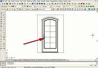
30. Offset and adjust the door tracing to create the window opening in the door (see Figure 8).


Figure 8: Trace the raster image.
(click image to enlarge)

31. Select Draw > Solids > Extrude from the Main toolbar.

32. Select both the door tracing and the offset, and press the Enter key.

33. Enter 1.75 (doors are typically 1-3/4" thick) at the Command line when prompted to specify the height of extrusion, and press the Enter key.

34. Press the Enter key again to accept 0 for the taper (because there is no taper).

35. Select Modify > Solids Editing > Subtract from the Main toolbar.

36. Select the outside door and press the Enter key.

37. Select the inside (the offset) and press the Enter key.

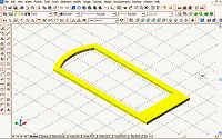
You have now created a solid model of the door (see Figure 9).


Figure 9: The solid model of the door.
(click image to enlarge)

38. Make the Mullions layer the Current layer and trace the mullions.

39. Change the mullions into a single polyline and extrude them 1" (see Figure 10). This procedure is similar to the one described in Steps 30-33.


Figure 10: The solid door and mullions.
(click image to enlarge)

40. Select Modify > 3D Operation > Rotate 3D from the Main toolbar.

41. Select the door and mullions and press the Enter key.

42. Select X axis at the Command line and press the Enter key.

43. Using the Endpoint object snap, select the lower-left corner of the door.

44. Enter 90 at the Command line for the rotation angle and press the Enter key.

You have now put the door and mullions on a vertical alignment (see Figure 11).


Figure 11: 3D ROTATE the door and mullions.
(click image to enlarge)

45. Turn on the Jamb layer, unlock it, and make it current. (Make sure the jamb tracing is a polyline.)

46. Select Desktop > Profiles > Convert polyline to Profile Definition from the Main toolbar.

47. Select the Jamb polyline, and pick a point in the middle of the polyline.

48. At the Command line accept New, and press the Enter key to bring up the New Profile Definition dialog box.

49. In this dialog box enter the name French Jamb and click the OK button.

50. Save the file.

You have now created a copy of the Standard Style (it is automatically named Standard 2).


Placing the New Door, Mullions, and Jamb into the New Door Style
1. Change to SW Isometric View.

2. Select Design > Doors > Door Styles from the Main menu to bring up the Style Manager.

3. At the Style Manager select the Standard door, right-click, and select Copy from the contextual menu.

4. Right-click again and select Paste from the contextual menu.

5. Rename (Standard 2) to French door Single and click the OK button.

6. Place a 10'-high standard wall approximately 12' long in your drawing.

7. Select the wall, right-click, and select Insert > Door from the contextual menu to bring up the Add Doors dialog box.

8. At the Add Doors dialog box, select the French door Single from the Style drop down list, and set the size to 3'-0" X 6'-8".

9. Place the French door Single Style 3'-0" X 6'-8" door in the wall (see Figure 12).
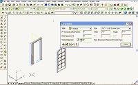

Figure 12: Place a door in a wall.
(click image to enlarge)

10. Select Draw > Block > Make from the Main menu to bring up the Block Definition dialog box.

11. In this dialog box create the name French Door and Mullions.

12. Select the door and mullions that you created and pick an insertion point at the bottom left of the door (see Figure 13).
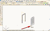

Figure 13: Block the new solid door.
(click image to enlarge)

You have now created a block of the door.

13. Select the door in the wall, right-click and select Edit Door Style from the contextual menu to bring up the Door Style Properties dialog box.

14. In this dialog box, select the Display Props tab.

15. Attach an override to the Door Style by selecting the first check box under the Attached column (see Figure 14).

16. Make sure Model is selected on the Display Props tab.
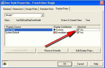

Figure 14: Attach an override to the Door Style.

17. Click the Edit Display Props button to bring up the Entity Properties dialog box.

18. In this dialog box, select the Other tab.

19. Click the Add button to bring up the Custom Block dialog box (see Figure 15).
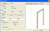

Figure 15: Bring up the Custom Block dialog box.
(click image to enlarge)

20. In this dialog box, click the Select Block button to bring up the Select A Block dialog box (see Figure 16).
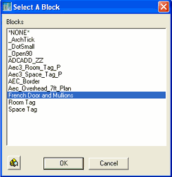

Figure 16: Bring up the Select A Block dialog box.

21. In this dialog box select the door block you made (French Door and Mullions), and click the OK button, which returns you to the Custom Block dialog box.

You have now added the door to French Door style.

22. In the Custom Block dialog box, select the Leaf Component and All radio buttons, set the Y Insertion Point to Back (see Figure 17), and click the OK button to return to the Entity Properties dialog box.
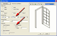

Figure 17: Set the Y Insertion Point to Back.
(click image to enlarge)

23. In this dialog box select the Layer/Color/Linetype tab.

24. Clear the Door Panel and Swing Visible icons (see Figure 18). Note that French Door and Mullions now appears as a component.

25. Click the OK button to finish and return to the drawing screen (see Figure 18).
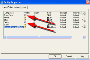

Figure 18: Clear the Door Panel and Swing Visible icons.

To create the jamb:

26. Select the door in the wall, right-click, and select Edit Door Style from the contextual menu. The Door Style Properties dialog box for the French Door Single component displays.

27. Select the Design Rules tab (if it is not already current), select the Custom radio button, and from the drop-down list that appears select French Jamb (see Figure 19).

28. Click the OK button to close this dialog box and return to your drawing (see Figure 19).
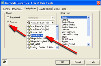

Figure 19: Select the custom jamb.

29. Save this file. You may want to reuse it.

You are done! You now have a new custom door style to use and share. Take the door for a test-drive by placing several with different setting Openings (percent) (see Figure 20).
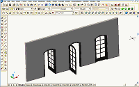

Figure 20: Customized door placed in sample wall.
(click image to enlarge)

Conclusion
You can apply the techniques we've been working with in this tutorial to windows, curtain walls, and window assemblies. Styles are an important part of the productivity benefits of using Autodesk Architectural Desktop 3.3. Once mastered, the creation of customized Styles will allow you to quickly and easily add new content to your drawings.

Don't forget to go to the Point A Download Center, where you'll find a variety of customized doors and windows. Check them out. And if you create some new Styles, share them.

Good Luck, Ed Goldberg.


H. Edward Goldberg, AIA, is a practicing architect and industrial designer, as well as Coordinator of Industrial Design at Towson University in Towson, Maryland. Ed can be reached at h.e.goldberg@verizon.net.