If
These Walls Could Talk
by: Ed Goldberg
URL: http://localhost/gotoPointA.jsp?dest=2_8gold
|
In last month's column we discussed some of the tools for creating, modifying, and automatically cleaning up walls that you'll find in Autodesk® Architectural Desktop 3 and 3.3. In this month's column, we're doing more of the same, looking at some new tools—Wall Justification, for example—that will further simplify the essential work that you do with walls in all your projects. Once again, we will use the four-view drawing template we created last month. If you do not have that template, you can download it from here (90 KB). Starting
a new drawing with the Wall_tutorial template 2. In this dialog box, select the Use a Template icon and select the Wall_tutorial template from the drop-down list.
3. Change to the Work_3D layout tab. Placing
the toolbars 2. Select the ARCARCHX option to open the Autodesk Architectural Desktop Toolbar Selector. (see Figure 1.)
3. At the Architectural Desktop Toolbar Selector, check the Walls and Wall Tools toolbars. When the toolbars appear, place them in a convenient place on your screen.
4. Repeat this process with the ACAD option and place the View and Shade toolbars. Converting
lines to walls and Wall Justification 2. Select the Convert to Walls icon and then select the 10' line. When asked "Erase layout geometry?" enter Y at the Command line and press the Enter to bring up the Wall Properties dialog box. 3. In this dialog box, select the CMU-8 Rigid-1.5 Air-2 Brick-4 Furring wall, and press the OK button to finish the command. You should now have a wall adjacent to a line. 4. Zoom in so the wall and line fill the viewport. Change to Paperspace by clicking the PAPER/MODEL button below the Command line. 5. Select the Top View viewport border and right-click to bring up the contextual menu. |
)
|
Locking
the display
2. Zoom in on the Top View so that it fills your screen, and then change to Modelspace by again clicking on the PAPER/MODEL button below the Command line. You get the view shown in Figure 3.
3. Select the Wall, and right-click to bring up the contextual menu. 4. Select Wall Modify from the contextual menu, which brings up the Modify Walls dialog box. 5. In this dialog box, select the Justify drop-down list, change the justification to Left, and press the Apply button. Repeat this process while changing and reapplying the different justifications. Notice the difference between Center and Baseline Justification (see Figure 4).
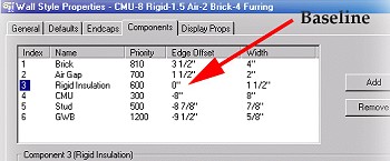
Understanding
the Baseline Justification 2. In this dialog box, select the Components tab. The Components tab in the Wall Style Properties dialog box is used to set the components such as brick, insulation, and so on as well as their vertical location within the given wall style. Notice in this tab that the Edge Offset of the Rigid Insulation is 0"; this makes that edge the baseline. All other materials have either a positive or negative Edge Offset in relationship to the Baseline.
Conclusion Our work with walls will continue in next month's tutorial. |
H. Edward Goldberg, AIA, is a practicing architect and industrial designer, as well as Coordinator of Industrial Design at Towson University in Towson, Maryland. Ed can be reached at h.e.goldberg@verizon.net.