|
Visual
Audit
The Visual Audit
routine results in a quick display of all non-Autodesk Architectural
Desktop objects in a drawing.
To enable this
feature, enter Visualaudit at the command line or from the
main menu, select Desktop > Utilities > Visual Audit (see Figure 10).
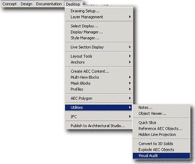
Figure 10: Starting the Visual Audit routine.
To use this
routine:
1. Start a new
drawing using the AEC arch [imperial] template, and select the Model
Layout, top view.
2. From the Draw
menu, place various entities such as circle, rectangle, line, ellipse,
and so on in the layout.
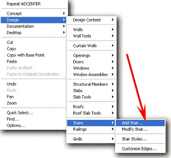
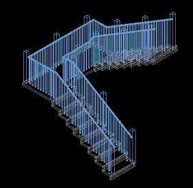
3. From the Design
menu place various intelligent AEC objects such as stair, wall, window,
door, and so on in the layout.
4. At the command
line enter Visualaudit or from the main menu select
Desktop > Utilities > Visual Audit (see Figure 10).
All the
intelligent AEC objects disappear from your screen (with the exception
of text, mtext, and dimension lines), revealing only AutoCAD entities.
5. Press the Esc
or Enter key, or click the mouse to return all the AEC objects to the
screen.
Generate
Napkin Sketch
Use this feature
when you want to give a drawing a "sketched" look. A sketched object is
overlaid on the original drawing. You control whether the sketch is
tight, loose, or messy and the plot output scale. Keep in mind that
using this feature can significantly increase drawing file size. For 3D
sketches, you'll achieve the best result by first creating a hidden-line
projection, and then using the Napkin Sketch feature on the results.
To enable this
feature, at the command line, enter Napkin or from the
main menu, select Documentation > Napkin Sketch (see Figure 11).
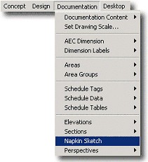
Figure 11: Accessing the Napkin Sketch feature.
Creating
the House Perspective
1. Start a new
drawing using the Aec arch [imperial] template, and select the Model
Layout, top view.
2. Place two
rectangles 50'x 30' and 20'x 25' (see Figure 12).
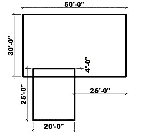
Figure 12: Place rectangles to create basis for house.
3. Trim the
rectangles to look like those in Figure 13.
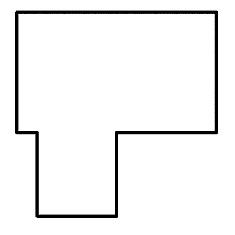
Figure 13: Trim the rectangles.
4. Select Design >
Walls > Convert to Walls from the main menu.
5. Select all the
trimmed rectangles with a window selection, and press the Enter key.
6. Enter Y
(for Yes) at the command line to erase the layout geometry and
press the Enter key to bring up the Wall Properties dialog box.
7. In this dialog
box, select the Standard wall drop-down list and click OK.
Converting the
Rectangles into Walls
1. Select the
walls, right-click, and select Door from the context menu.
2. Insert doors in
the walls.
3. Select the
walls again, right-click, and select Window from the context menu.
4. Insert windows
in the walls.
5. Right-click in
the viewport and select Design > Roofs > Convert to Roof from the
context menu.
6. Select all the
walls with a window selection and press the Enter key.
7. Enter N
(for No) at the command line when prompted "Erase layout
geometry?" to open the Modify Roof dialog box.
8. In this dialog
box, click OK.
You have now
created the house (see Figure 14).
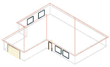
Figure 14: The house.
To place the
building in perspective:
1. Select the
Orbit tool from the Standard toolbar.
2. Place the house
in Hidden Shade Mode and Perspective Projection.
Using
Hidden-Line Projection
1. Select the
Desktop > Utilities > Hidden Line Projection from the main menu, and
select the building.
2. Enter 0,0
at the command line and press the Enter key.
3. Enter Y
(for Yes) at the command line when prompted "Insert in Plan
View?"
4. Return to the
top view, and erase the building you first created leaving the flat
Hidden Line Projection drawing.
Applying
Generate Napkin Sketch
1. Enter Napkin at
the command line or select Documentation > Napkin Sketch from the
main menu to open the Napkin Sketch dialog box.
2. In this dialog
box, select the Tight, Loose, or Messy radio button, and select an
Intended Plot Scale (see Figure 15).
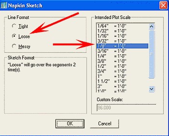
Figure 15: The Napkin Sketch dialog box.
3. Select the flat
Hidden Line Projection drawing, and press the Enter key.
Your flat Hidden
Line Projection drawing modifies to look "hand-drawn" (see Figure 16).
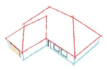
Figure 16: Generate Napkin Sketch creates a "hand-drawn" look.
You can adjust
Napkin by lowering or raising the plot scale. And you can even take the
drawing into Autodesk® Architectural Studio and paint it for a
presentation (see Figure 17).
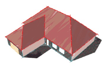
Figure 17: You can take the drawing into Autodesk Architectural
Studio for painting.
Conclusion
Whether it is presentation or documentation, the tools provided with the
new Productivity Presentation Extension will help you work faster and
smarter. It's one more way Autodesk is making Autodesk Architectural
Desktop the best software program available for architects and
designers.
|