 Architectural
Desktop: Elevation Styles
by Edward Goldberg
Architectural
Desktop: Elevation Styles
by Edward Goldberg
URL: http://pointa.autodesk.com/gotoPointA.jsp?dest=15809
Recently a Toplines reader asked me to discuss Autodesk® Architectural Desktop 3.3 Elevation Styles in a column.
This tutorial, with its three short exercises, will familiarize you with some of the basic uses of this valuable automated object.
I will cover other aspects of Elevation Styles in a future tutorial. A style is a group of properties assigned to an object that determine the appearance and function of the object.
The style of a 2D elevation allows you to control the linework of a 2D elevation, by setting rules in the style properties. These rules determine how different parts of the elevation display in your drawing. You can also change the display of individual lines in the elevation, and save your changes in the 2D elevation object.
Exercise 1: Using Elevation Styles to Show Vertical 2D Orthographic Representations of a Building or Room
Creating a Simple Building
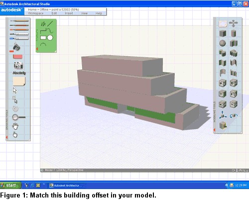
Using Autodesk® Architectural Studio or the Architectural Desktop Mass Elements tools, create a building 30' wide by 90' long with setbacks similar to those shown in Figure 1.
|
Note: If you are
using Architectural Studio, refer to my tutorial
on using Architectural Desktop and Architectural Studio software together.
|
If you are not using Architectural Studio, please refer to my tutorial Mass Modeling the Autodesk Architectural Desktop Way, and create the model in Autodesk Architectural Desktop.
Exporting the Model to
Architectural Desktop
With Architectural Studio running, open Architectural Desktop 3.3 and:
1. Start a new drawing using the Aec arch [imperial] template, and select the Mass-Group Layout. Minimize Architectural Desktop.
2. Maximize Architectural Studio and select Export > Architectural Desktop from the drop-down list at the bottom-left corner of the electronic 3D tracing paper to export your Architectural Studio model to Architectural Desktop as Mass Elements.
3. Close Architectural Studio.
Creating the Walls in
Architectural Desktop 3.3
1. Maximize Architectural Desktop 3.3.
2. Select View > Viewports > 1 Viewport from the Main toolbar and create one viewport in the Mass-Group Layout.
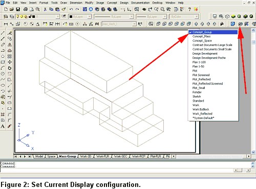
3. Select the Set Current Display Configuration icon from the AEC Setup toolbar, and check the Concept_Group configuration. Zoom Extents in the viewport, and change to SE Isometric View (see Figure 2).
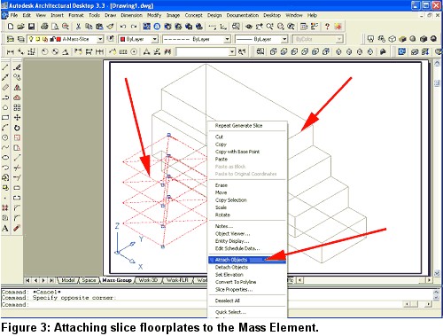
4. Select Concept > Slice Floorplates > Generate Slice from the Main toolbar, and generate four slices 10' high.
Select all the slice floorplate indicators, right-click, and select Attach Objects from the contextual menu (see Figure 3).
5. Select all the Mass Elements, and press the Enter key.
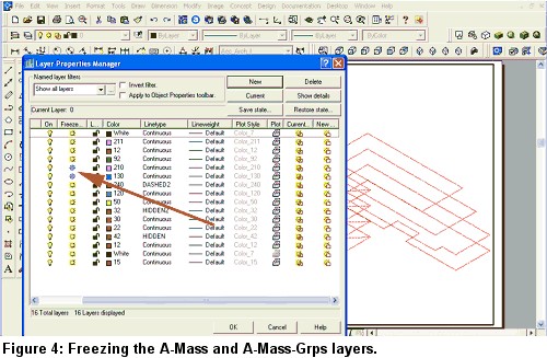
6. Freeze the A-Mass and A-Mass-Grps layers to hide the Mass Elements (see Figure 4).
7. Select Concept > Slice Floorplates > Convert to Polyline from the Main toolbar, select all the slice floorplates, and press the Enter key to create polylines.
|
Note: In
Autodesk Architectural Desktop, you can quickly convert polylines to
walls.
|
8. Freeze the Mass-Slice layer to hide the slice floorplates leaving only polylines.
Creating the Walls
1. Select Design > Walls > Convert to Walls from the Main toolbar, and then starting with the first polyline, select every other polyline, and press the Enter key.
2. Enter Y at the Command line to erase layout geometry, and press the Enter key to bring up the Wall Properties dialog box.
3. Select Standard from the Style tab.
4. Select the Dimensions tab, and set the B- Base height to 10'.
5. Set Justify to Baseline and press the Enter key to create the walls.
6. Change to the Work-FLR layout.
7. Change the viewport to Front View.
8. Select Design > Curtain Walls > Convert Wall to Curtain Wall from the Main toolbar.
9. Select the top three floor walls with a Crossing selection and press the Enter key.
10. Accept Baseline at the Command line and press the Enter key to bring up the Curtain Wall Styles dialog box.
11. Select Standard and press the OK button.
12. Enter Y (for Yes) at the Command line, and press the Enter key.
Your building now has curtain walls on the upper levels.
Adding Doors
1. Change to an Isometric view.
2. Select Design > Add Door from the Main toolbar to bring up the Add Doors dialog box.
3. Select Hinged-Double 6'0" x 6'8", and select the Automatic Offset/Center check box.
4. Add entrance doors at the lower floor.
For this exercise, the building is complete. Save a copy of this file because in a future tutorial we will add a roof and floor slabs to this building (see Figure 5).
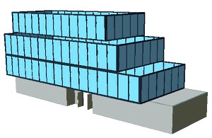
Figure 5: The completed building for this exercise.
Exercise 2: Creating the Elevation Line and the Elevation Object
1. Change the viewport to Top View.
2. Select Documentation > Elevations > Add Elevation Line from the Main toolbar.
3. Left-click at the front left of the building.
4. Drag and click again at the front right of the building. An Elevation Object appears (see Figure 6).
Figure 6: Creating the Elevation Line.
5. Select the Elevation Object, right-click, and select Generate Elevation from the contextual menu to bring up the Generate Section/Elevation dialog box.
6. Select 2D Section/Elevation Object with Hidden Line Removal as Result Type.
7. Select Section_Elevation as display Set.
8. Select the Select Objects arrow, select the entire building, and then press the Enter key to return to the Generate Section/Elevation dialog box.
9. Select the New object radio button under Placement.
10. Select the Pick Point arrow and select a point to the right of the building.
11. When the Generate Section/Elevation dialog box reappears, press the OK button to create the elevation (see Figure 7).
Figure 7: Generating the 2D Elevation Object
Exercise 3: Controlling Color by Subdivision
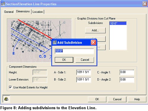
1. Select the Elevation Object, right-click, and select Elevation Line Properties to bring up the Section/Elevation Line Properties dialog box.
2. Select the Add button to bring up the Add Subdivision dialog box. Accept the default 10'0" (see Figure 8).
You have now added a new subdivision to the Elevation Object (see Figure 9).
Figure 9: The added Subdivision Line.
3. Select the generated elevation, right-click, and select Edit 2D Section/Elevation style from the contextual menu to bring up the 2D Section/Elevation Styles dialog box.
4. Select the Display Props tab and press the Edit Display Props button to bring up the Entity Properties dialog box.
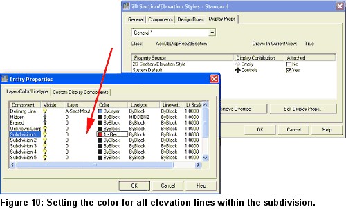
5. Set the color of Subdivision 1 to red, and press the OK buttons to close all dialog boxes (see Figure 10).
6. Select the elevation again, right-click, and select Update from the contextual menu.
Note that the second and third floors turn red. That is because they are located between subdivisions 1 and 2.
Use Subdivisions to control the color of lines and lineweights within their subdivision area (see Figure 11).
Figure 11: The second and third floors turn red.
To set elevation line types and colors in the elevation depending on component color:
1. Change to SW Isometric View, and Zoom close to the curtain wall.
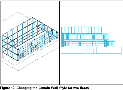
2. Select the second- and third-floor front walls, right-click, and select Edit Curtain Wall Style from the contextual menu. The Curtain Wall Style Properties dialog box displays.
3. Select the curtain wall, right-click, and select Modify Curtain Walls from the contextual menu to bring up the Modify Curtain Walls dialog box.
4. Change the Style to Precast Panel.
5. Repeat Steps 1-11 under "Creating the Elevation Line and Elevation Object" to create a new Elevation Object (see Figure 12).
6. Select the Precast curtain wall, right-click, and select Edit Curtain Wall Unit Style, which opens the Curtain Wall Unit Style Properties dialog box.
7. Select the Display Props tab.
8. At the bottom of that tab, press the Edit Display Props button to bring up the Entity Properties dialog box.
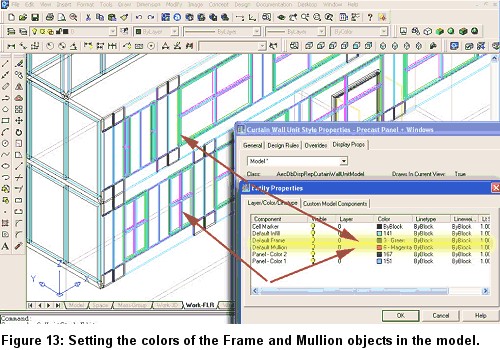
9. Change the colors of the Default Frame and Default Mullion for the curtain wall unit to green and magenta (see Figure 13).
10. Change the view back to Top View.
11. Select the generated elevation, right-click, and select Edit 2D Section/Elevation style from the contextual menu. The 2D Section/Elevation Styles dialog box displays.
12. Select the Components tab.
13. Press the Add button on that tab, and create three new components. Name them Frame, Mullion, and Panel (see Figure 14).
Figure 14: Creating components by adding to the 2D Section/Elevation Styles
dialog box.
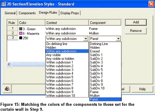
14. Select the Design Rules tab, and add three rules.
15. Match the colors of the components to those set for the curtain wall in Step 9, and set the Panel color to 250. Set the other fields as shown in Figure 15.
16. Select the Display Props tab.
17. Select the Edit Display Props button at the bottom of that tab to bring up the Entity Properties dialog box.
18. Select the Custom Display Components tab.
19. Press the Add button and add three components. Name them Frame, Mullion, and Panel (see Figure 16).
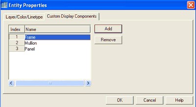
Figure 16: At the Entity Properties dialog box select the Custom Display
Components tab.
20. Select the Layer/Color/Linetype tab.
21. Set the colors that you wish to display in the Elevation Object for each component (see Figure 17).
22. Click OK when you are finished.
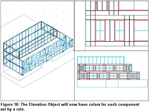
Figure 17: Set the colors that you wish to display in the Elevation Object.
The Elevation Object will now have colors for each component set by a rule and the colors of the model (see Figure 18).
Conclusion
The style of a 2D elevation allows you to control the linework of a 2D elevation
by setting rules in the Style Properties. These rules determine how different
parts of the elevation display in your drawing. You can also change the display
of individual lines in the elevation and save your changes in the 2D Elevation
Object. There are many more controls; I will explain more of the features of 2D
elevation objects in another tutorial. Once mastered, and styles saved, Autodesk
Architectural Desktop 3.3 AEC 2D elevation objects will be a productive asset in
your practice.
Good Luck,
Ed Goldberg
H. Edward Goldberg, AIA, is a practicing architect and industrial designer, as well as Coordinator of Industrial Design at Towson University in Towson, Maryland. Ed can be reached at h.e.goldberg@verizon.net