 by: Ed Goldberg
URL: http://pointa.autodesk.com/gotoPointA.jsp?dest=2_11gold
Introduction
to Column Grids
 by: Ed Goldberg
URL: http://pointa.autodesk.com/gotoPointA.jsp?dest=2_11gold
The basic structure in most commercial buildings is the column grid. The work of each design professional involved in this sort of project—architect, structural engineer, and mechanical engineer—depends on the location of the grid. Autodesk® Architectural Desktop 3 and 3.3 offers parametric tools that enable you to control, label, and dimension these grids. Because these are intelligent parametric tools, you can easily modify your grid allowing quick changes in the structural part of your design. In this tutorial, you will learn how to use some of these tools.
You can access the column grid tools in the software in any one of three ways:
Creating the Column
Grid with Columns Attached
1. Create a new drawing using the Walls_Tutorial template. If you do not have
this template, please download it from here
(91 KB).
2. When the Drawing Editor appears, select the Work_3D layout tab.
3. Activate the top-left viewport (Top View) by clicking in that viewport.
4. Right-click to bring up the contextual menu and select Design > Grids > Add Column Grid. The Add Column Grid dialog box displays.
5. From the Shape drop-down list select Rectangular then enter 60'-0" in the X-Width box and 30'0" in Y-Depth box.
6. Select the Divide By check boxes for both X-Width and Y- Depth, and set the amount of division to 2 and 3 respectively (see Figure 1).

Figure 1: The Add Column Grid dialog box is the entry path for creating
column grids.
(click image to enlarge)
7. Click the Column button, which opens the Add Columns dialog box.
8. From the Style drop-down list, select the Standard style column; in the Length box enter 8'-0"; from the Justify drop-down list, select Middle Center of the column; leave all other selections as shown in (Figure 2).
![]()
Figure 2: Select the type of column for the column grid from the Add Columns
dialog box.
(click image to enlarge)
9. Click Close, which returns you to the Top View, and click in that view to place the column grid with columns at all grid nodes.
10. Perform a ZOOM EXTENTS in all viewports as shown in (Figure 3).
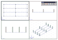
Figure 3: The column grid is placed with columns automatically positioned at
all node intersections.
(click image to enlarge)
You have now created a column grid with columns anchored at all the nodes.
Labeling the Column
Grid
Architects and engineers use a labeling convention when labeling column grids.
Usually they label one direction of the grid by number and the other direction
by letter. This allows each column, or node, to have an alphanumeric listing.
Autodesk Architectural Desktop software has automated this process, but you can
still customize it to fit your needs.
1. Select the column grid and right-click to bring up the context-sensitive menu.
2. Select Labels. The Column Grid Labeling dialog box displays, which is where you set the alphanumeric characters for X- and Y-labeling (see Figure 4).
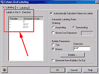
Figure 4: Column grid labeling is controlled in the Column Grid Labeling
dialog box.
(click image to enlarge)
3. In the Labels in the X-Direction pane, enter A under the Number column.
4. Select the Automatically Calculate Values for Labels check box; select the Descending radio button in the Automatic Labeling Rules pane; and clear the Top check box in the Bubble Parameters pane. The letters B and C automatically fill the other spaces in the Number column.
5. Change 4'-0" to 10'-0" in the Extension box in the Bubble Parameters pane, and click OK to complete the command and alphabetically label the column grid in the X- direction (see Figure 5).
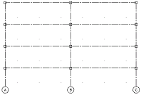
Figure 5: The X-direction is labeled alphabetically.
(click image to enlarge)
6. Repeat Steps 3-5 under the Y-Labeling tab of the Column Grid Labeling dialog box, but this time enter 1 (not A) in the first space under the Number column.
7. Make sure all settings are as shown in Figure 6.
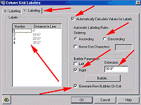
Figure 6: The Y-direction is labeled numerically.
(click image to enlarge)
8. Click OK to complete the command and numerically label the column grid in the Y-direction (see Figure 7).
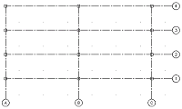
Figure 7: The totally labeled grid.
(click image to enlarge)
Labeling the Column Grid
The column grid will be automatically dimensioned (see Figure 8).
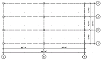
Figure 8: The grid totally labeled and dimensioned.
(click image to enlarge)
Modifying the Labels
If you wish to modify the label ordering, bring up the Column Grid Labeling
dialog box, and modify any of the numbers or letters. If the Generate New
Bubbles on Exit check box is selected, any changes to the alphanumeric system
will be updated on the drawing.
Because this is a beginning tutorial on Autodesk Architectural Desktop 3 and 3.3, we've only looked at a few of the capabilities of its column grid tools. Next month, we will explore these grids further, discovering the ease with which they can be extended and modified to work within any building plan